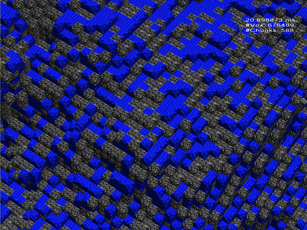
One year ago I have written a post with the same header. Now I am back to the project Monolith and the 20ms frame time I got before was just unbearable. The observation that there are components consisting of the same voxel patterns again and again helped a lot to implement a new hybrid approach: Geometry-Shader-spawned cubes with ray marched volume textures.
Ray Marching Voxel Textures
As before I use optimized geometry shader instancing for boxes. But now I draw boxes down to the component level only (a component is a functional unit in monolith e.g. a thruster or a laser). Below that the geometry is static and it is affordable to store dense information for that, i.e. volume textures.
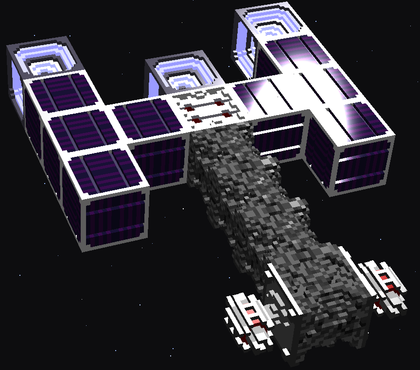
The laser weapons in the front demonstrate the effect of neighbor-sensitve sampling
Visualizing volume textures with ray marching is common sense and straight forward. Since I wanted to have a blocky look the ray can do steps from plane to plane in the uniform grid. The traversal can stop if any non-zero entry is found in the texture. It is possible to march through the texture without maintaining a floating point ray position. Therefore the initial texel position is determined and then in each iteration one of three dimensions is increased or decreased depending on the sign of the ray direction. The right dimension to modify is that which is closest to the next grid-plane in ray direction. Despite changing the texture coordinate, the plane distances must be updated which is a simple subtraction of the distance of the step. The chosen dimension in which the step was done has 0 distance then, so it is reset to the full projected distance between two planes.
The following fragment shader performs the ray marching. Additional to the explained ray marching voxelMask is introduced. This mask changes the appearance of the component dependent on the neighborhood. It is a code with a bit for each side and an additional one for non side dependent voxels. The texture contains a mask of the same kind too. Hence, a simple logic AND can decide between visible voxel or not. Additionally the geometry shader computes a LOD (mipmap) dependent on the view distance. Doing this in the fragment shader would cause artifacts, because a LOD-seem can run through a single component which would create little holes.
|
1 2 3 4 5 6 7 8 9 10 11 12 13 14 15 16 17 18 19 20 21 22 23 24 25 26 27 28 29 30 31 32 33 34 35 36 37 38 39 40 41 42 43 44 45 46 47 48 49 50 51 52 53 54 55 56 57 58 59 60 61 62 63 64 65 66 67 68 69 70 71 72 73 74 75 76 77 |
flat in vec3 gs_objectPosition; flat in ivec3 gs_neighbor_material_mipmap; in vec3 gs_texCoord; out vec4 fragColor; uniform isampler2DArray u_componentTex; ... void main() { // Determine which voxels can be sampled at all (dependent on neighborhood) int voxelMask = 0x40 | ((~gs_neighbor_material_mipmap.x) & 0x3f); int materialIndex = gs_neighbor_material_mipmap.x >> 24; ivec2 codes; codes.x = gs_neighbor_material_mipmap.y; // Find view direction in component-space vec3 chunkSpacePos = gs_objectPosition + gs_texCoord - 0.5; vec3 viewDir = normalize((vec4(chunkSpacePos, 1) * c_mWorldView).xyz); vec3 chunkSpaceDir = viewDir * mat3x3(c_mInverseWorldView); // Number of pixel must be equal in all directions (can theoretically be changed // if required). Used for ray marching the texture. int texSize = c_maxTexRes / (1 << gs_neighbor_material_mipmap.z); // Initialize ray marching algorithm ivec3 dirSign; dirSign.x = chunkSpaceDir.x < 0.0f ? -1 : 1; dirSign.y = chunkSpaceDir.y < 0.0f ? -1 : 1; dirSign.z = chunkSpaceDir.z < 0.0f ? -1 : 1; vec3 voxelPos = gs_texCoord * (texSize - 0.00001); ivec3 rayPos = ivec3(voxelPos); vec3 absDir = abs(chunkSpaceDir); vec3 projLength = 1.0 / (absDir + 0.0001); vec3 d = voxelPos - rayPos; if(dirSign.x == 1) d.x = 1-d.x; if(dirSign.y == 1) d.y = 1-d.y; if(dirSign.z == 1) d.z = 1-d.z; d *= projLength; if( materialIndex != 0 && texSize > 1 ) { // Ray march until a voxel is set in the current configuration codes = texelFetch(u_componentTex, ivec3(rayPos.x + rayPos.y * texSize, rayPos.z, materialIndex), gs_voxel_material_mipmap.z).xy; while((codes.y & voxelMask) == 0) { if(d.x < d.y || d.z < d.y) { if(d.x < d.z) { rayPos.x += dirSign.x; d.yz -= d.x; d.x = projLength.x; } else { rayPos.z += dirSign.z; d.xy -= d.z; d.z = projLength.z; } } else { rayPos.y += dirSign.y; d.xz -= d.y; d.y = projLength.y; } if(any(greaterThanEqual(rayPos, ivec3(texSize,texSize,texSize))) || any(lessThan(rayPos, ivec3(0,0,0)))) discard; codes = texelFetch(u_componentTex, ivec3(rayPos.x + rayPos.y * texSize, rayPos.z, materialIndex), gs_voxel_material_mipmap.z).xy; } } // Estimate normal from the plane we intersected d = abs(d - projLength); vec3 normal; if(d.x < 0.0001) normal = -dirSign.x * vec3(c_mWorldView[0][0], c_mWorldView[1][0], c_mWorldView[2][0]); if(d.y < 0.0001) normal = -dirSign.y * vec3(c_mWorldView[0][1], c_mWorldView[1][1], c_mWorldView[2][1]); if(d.z < 0.0001) normal = -dirSign.z * vec3(c_mWorldView[0][2], c_mWorldView[1][2], c_mWorldView[2][2]); normal = normalize(normal); ... } |
Results - Incredible!
The gain is much larger than hoped. The new hybrid approach takes only a few milliseconds (3-4) on the notbook GPU GTX850M. Before this took over 20ms. The new bottlenecks seem to be driver overhead (the GUI in main menu also takes 3ms) and bad scheduling. Well, I immediately increased the component resolution from 8 to 16 cubic which ended in a bit more than 4ms for really many voxels. Unfortunately the new approach is more sensitive to screen resolution but even so it is on the good side of 16ms. The image shows 62663 components (stone and water) with 16x16x16 voxels each. So the total theoretical amount of voxels in the image is around 256,667,000 (a quarter gigavoxel) whereby the effective number is much smaller (there are only 1M pixels). However the old render approach would have scheduled approximating 4 million voxels for the same image which is much more than 62 thousand.
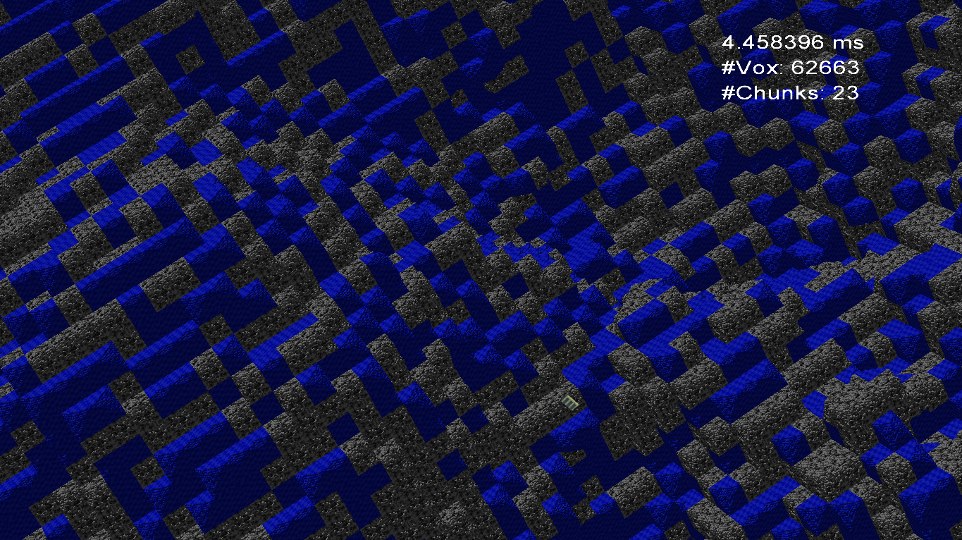
Approximating virtually 250,000,000 voxels (not all visible) in 4.45ms on a notbook GTX850M