Percentage Closer Filtering (PCF) is a common sampling/filtering technique to get rid of hard blocky shadow edges. It could be seen as a shadow-space antialiasing post process.
PCF Sampling tries to do an averaging over a neighbourhood to smooth out the edges. Therefore the shadow value will be interpolated between the 4 related texels from the shadow map. This is not done during sampling of z-values (as in solution 2), but after the comparison of the z values.
This smooths the edges but does not achieve a good antialiasing. Now the idea is to use look on the shadow value of a neighboured pixel and to average in between. For neighbours the same bilinear lookup with the same fractional parts for interpolation can be used. This can be done with a loop over an arbitrary large area. The averaging can further be weighted with a binomial or gaussian kernel to achieve even better results. Of course we don't want to do this for performance reasons.
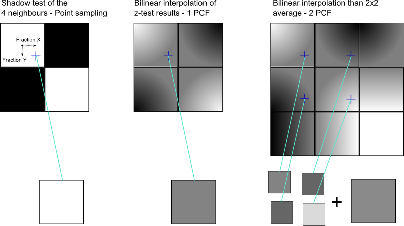
Schemes of Point, PCF 1x1 and PCF 2x2 sampling
Often a loop of 3x3 or 4x4 is used. In each turn a lookup is performed as descibed above. The the areas covered by these loops are 4x4 and 5x5 pixels, respectively. This also means that we load 9*4 and 16*4 texels to compute the shadow of one pixel. How this can be reduced I will descibe in my Faster PCF post.
Solution Attemps (working for other sampling techniques)
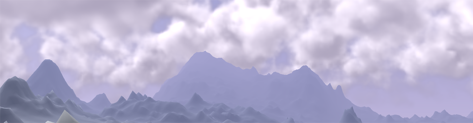
Shadow acne is a common artifact in shadow map techniques. Similar to z-fighting artifacts some sharp-edged shadow appear on surfaces which should not be shadowed at all. This effect emerge if the surface tangential plain and the light direction are nearly parallel.
Shadows only - Artifacts at surfaces and behind the "player" (middle)
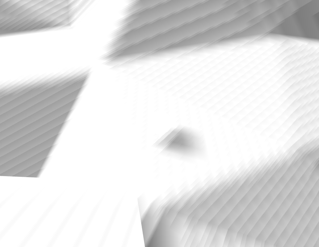
The image shows the shadows of a 4x4 PCF sampled shadow map. For the demonstration a coarse resolution of 1024x1024 was used for the whole scene and objects's front sides were drawn into it. The sphere in the middle only occupies 4 texels in the shadow map.
z-fighting: Even without PCF you can observe such streak patterns. This happens if the z values are very similar and the test fails due to precision errors or because the z buffer represents the value of a wrong pixel (e.g. some neighbour). A continuous map would solve this problem...
Solution 1: Offsetting
Often one subtract a constant value from the shadow map before comparing it to the current z value. This succeeds if the light is perpendicular to the surface. If they are not we get a new problem. Since point sampling chooses one or the other sample a pixel, a pixel in between is not represented properly. The smaller the angle between light and tangential plain the larger the difference of neighboured pixels in the shadow map. The consequence is that the offset needs to be much larger to avoid a wrong in-shadow-classification for the non represented points. Moreover the offset depends on the normal. One drawback of a larger offset is a new artifact called peter panning which is a gab between an object an its shadow.
→ Can be helpful if the offset is chosen depending on the normal, otherwise this is crap.
PCF on an interpolated Z-buffer.
Solution 2: Interpolating the Shadow Map
Yes, we can sample the shadow map with the standard linear sampler. This is correct if the surface between the two points in the shadow map is plain which it is most times. The gain of this is great and all artifacts are removed - for small samplers. Unfortunately this cannot be applied to PCF, because there we need the fraction of the pixel position for smoothing the shadow.
→ Solution for hard edged shadow sampling. Cannot be applied to PCF
Solution 3: Back faces and Offset-Meshes
Until now I have drawn front faces during the shadow map creation pass. Using back faces helps against z-fighting because the front faces always have a large offset to the back of the same model. Similar the mesh could be pumped along the normals to create a surface considering offset. This technique succeeds if the back faces are recognized as always in shadow. I would like to apply lighting to back faces too, so this would only move artifacts to the back side and causes further problems with self shadowing.
I did not tested Offset-Meshes which could be a good solution even for my scenario.
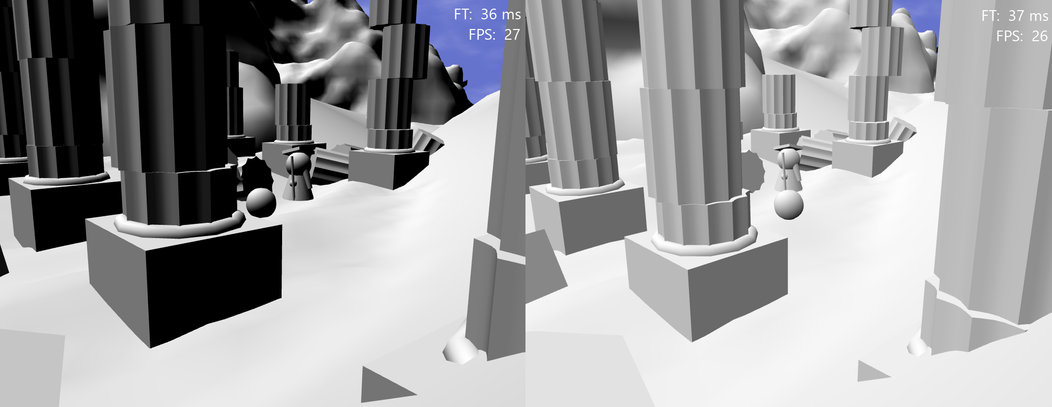
Comparison of <N,L> and <N,L>*0.5+0.5 (No ambient and other lighting) - Back faces on the left are "flat"
Now the PCF Sampling technique introduces an additional problem with the z-values. That we use the same interpolation factors is ok, but that we use the same z-value for the lookup of neighbours creates a lot of shadow acne. Moreover the direction in which we look on our neighbours is in light space! it would be better to go steps in the object space and transform that positions to light space. However this is the reason for an increase of artifacts.
The overall quality of PCF is good and supported by modern hardware. HLSL offers an intrinsic to do the lookup and the interpolation, or to fetch 4 pixel with the Gather command which I used in the code below.
Unfortunately none of the mentioned solutions 1-3 work for that kind of sampling (see pictures).
Solution (4) applied in Pathfinder

One mad+mul later
In graphics everything is a trick. Why bother with a correct algorithm if we can retouch the artifacts.
Observation: Obviously there is a boundary between some pixels where the z-lookup on the one side is very different from the one on the other side (→ streaks/banding). Close to this boundary the z-values must be very similar. I liked to smooth this boundary. My idea is to use the distance from the current z-value to the shadow map to find those edges. The distance must be small, because the values are very similar in the problem regions and lie on both sides of the shadow map value. So I multiply the shadow value with a clamped distance to get a linear decrease of light close to the boundary (see highlighted code).
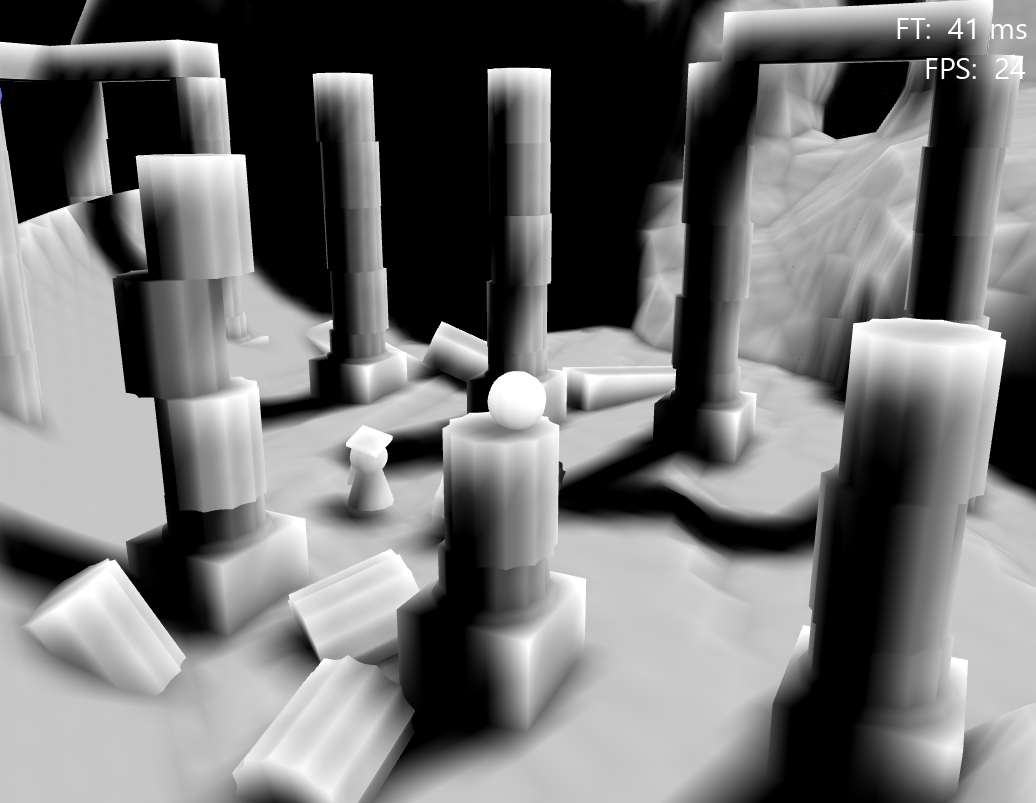
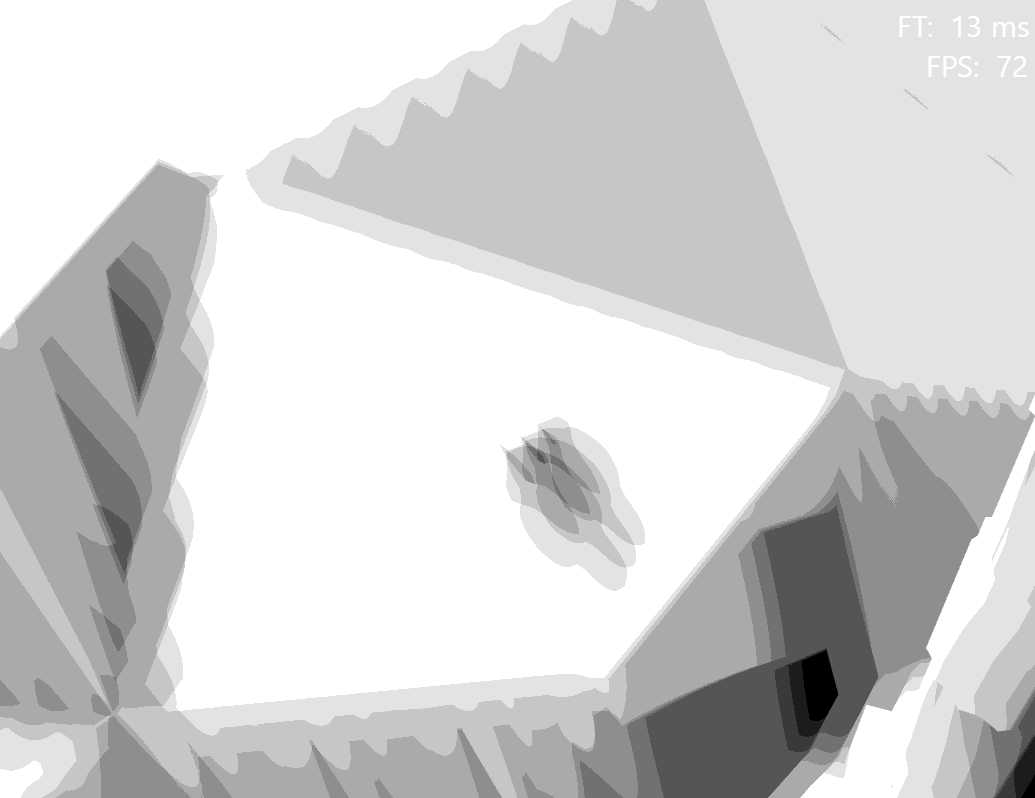
PCF 3x3 (No other lighting!), coarse map resolution (remember the sphere in the middle gets only 4 texels in the shadow map)
In consequence everything gets darker. For each point visible from the light the distance to the shadow map value is more or less 0. The whole scene would get black without the offset in line 33. This whole trick only requires two instructions for each lookup (mad_sat and mul). I replaced the streak artifacts by a new underexposure artifact. Well done! If you look on the results you will be satisfied. The new artifacts behaves a little bit like ambient occlusion. Yes, I got a very cheap ambient occlusion where other people use complex algorithms for ;-). But the higher the shadow map resolution the less this artifact appears. So I lost this nice side effect as I switched to cascaded shadow maps and increased the resolution.
|
1 2 3 4 5 6 7 8 9 10 11 12 13 14 15 16 17 18 19 20 21 22 23 24 25 26 27 28 29 30 31 32 33 34 35 36 37 38 39 40 41 42 43 |
// Compute the fraction of the coordinate and 1-x_frac, ... // With these factors a bilinear interpolation can be done with one // dp4 (dot product). // The order of the returned factors matches the pixel order of the // Gather command: (1-x)*(1-y), x*(1-y), (1-x)*y, x*y float4 bilinearFactors( float2 _vCoord ) { float4 vFrac; vFrac.xy = frac(_vCoord); vFrac.zw = 1-vFrac.xy; return vFrac.zxzx*vFrac.wwyy; } // Perform a parallel lookup of 4 shadow values and do a "corrected" // interpolation in between. float shadowLookup( Texture2D _ShadowMap, float2 _vCoord, float _fZ, float _fZScaled, float4 _vFrac, int2 _vOffset ) { // Sample and compare float4 vDepthSamples = _ShadowMap.Gather( g_PointSampler, _vCoord, _vOffset ); float4 vShadows = vDepthSamples > _fZ; // "Correction" of hard z-test edges. vShadows *= saturate(vDepthSamples*2048.0 - _fZScaled); // Interpolation return dot( vShadows.wzxy, _vFrac ); } // Compute the shadow value in [0,1] for the given postion float computePCFShadow3( Texture2D _ShadowMap, float3 _vWorldPos ) { float3 vLightSpaceCoord = mul(float4(_vWorldPos, 1), c_mLightViewProjection).xyz; // Is the current sample in the shadowmap or outside the volume? // Blend decreases the shadow intensity to the edges of the shadowmap. vLightSpaceCoord = vLightSpaceCoord*float3(0.5,-0.5, 1.0)+float3(0.5, 0.5, -0.0005); // perform PCF filtering on a 3 x 3 texel neighborhood float fSum = 0.0f; float4 vInterpolationFactors = bilinearFactors( vLightSpaceCoord.xy*c_fShadowMapResolution-0.5 ); float fZScaled = vLightSpaceCoord.z * 2048.0; for( int y = -1; y <= 1; y++ ) for( int x = -1; x <= 1; x++ ) fSum += shadowLookup(_ShadowMap, vLightSpaceCoord.xy, vLightSpaceCoord.z, fZScaled, vInterpolationFactors, int2(x,y)); return lerp( fSum/9.0, 1, fBlend); } |