Author Archives: Johannes

Drawing Beams

CoordinateGrid
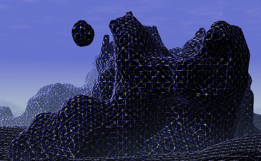
Shortly I discovered that drawing a proper beam is a really complex issue. I tried to draw a grid, but beams are also useful for lighting effects as god-rays or laser weapons. Of course you can draw a single line with just rendering lines (or wireframe). Unfortunately such lines are sharp and thin - good for a laser weapon but not for the rest. I started with single lines and found them not appropriate for my grid on FullHD resolution.

After expanding lines with a geometry shader I found some Problems:

  • Vertex coordinates behind the camera caused entire beams vanishing
  • Texture coordinate Interpolation got broken

I solved both by manually reimplementing pipeline stages which took me a day. So I though you might be interested in my solution.

Spanning the Beam with a Geometry Shader

The easy idea where everything begun: Create a billboard in the geometry shader.

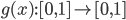
For an input of two vertices from a line compute a vector which is perpendicular to the line and the view direction. Add this new vector as offsets to the ends and emit a thin quad with two corners at on end and two at the other end. I did the offsetting directly in projection space to avoid the requirement for more matrices and transformations. This is not the common approach and might be confusing.

You can see the implementation in the code in the next section. I added a scaling * l1.w  to the offset vector to make the beam zoom invariant. This is because I will use it to render selections, ... of objects and don't want the handles to vanish at far distances. Later I discovered that this causes problem two and I removed it.

The next step was to smooth the quad borders in pixel shader. Therefore I created "texture coordinates" and used them to compute the distance of a fragment to the beam border.


Vanishing Triangles through Projective Space

Everything worked fine and than I enlarged my grid...

It is a matter of fact that if a vertex of a triangle is behind the camera the full triangle is culled. This is because in perspective space a vertex behind the camera has undefined coordinates - the camera itself is a singularity. It has nothing to do with the clipping algorithm, which would work well if a vertex is between near plane and camera. To avoid the negative coordinates you need to do clipping of the triangle yourself before perspective division.

The clipping must do two things: Move the vertex and interpolate its data. The lines 24-34 are doing this. Since I would like to clip a ray it becomes easier than with triangles. I project the end points along the ray direction to the nearplane. For a triangle do that on each edge. Important: the direction is the full 4D vector in homogeneous space. To figure that out I required most of the time.

 Perspective Interpolation

GridWOPerspective

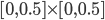
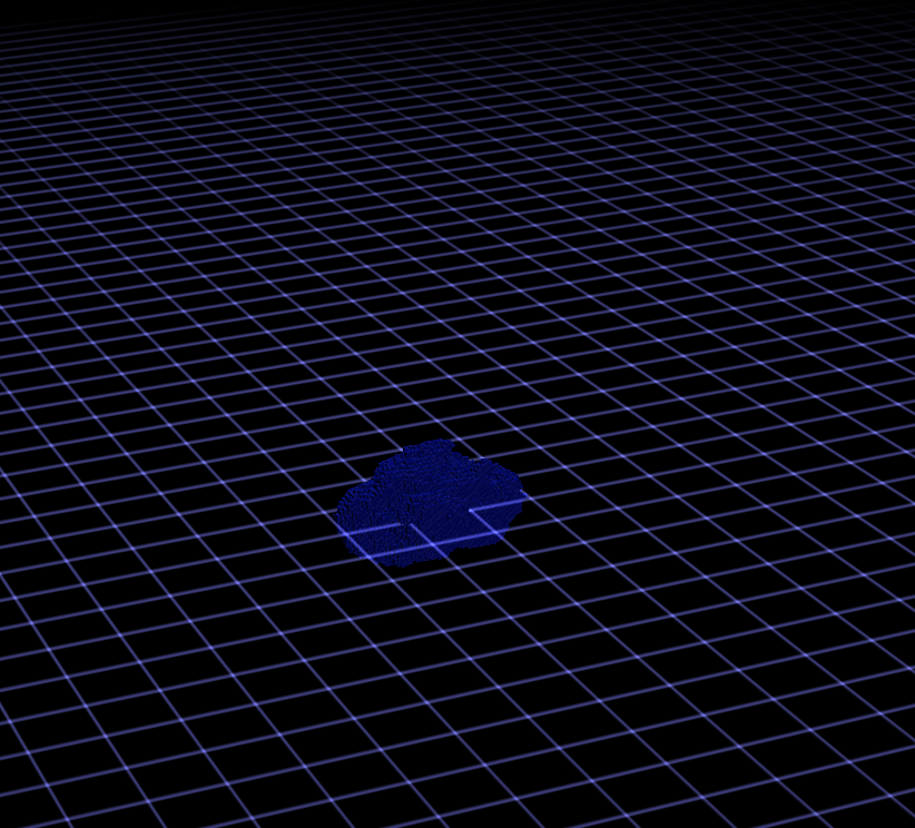
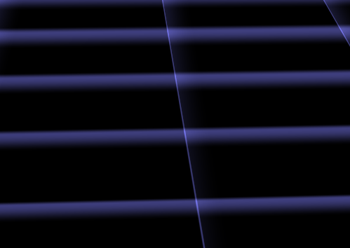
Without perspective correction

For any data interpolated over a triangle in screen space artifacts appear. If you search for the heading you will find pictures illustrating the problem. The first picture on the right also shows what happens when doing non-corrected interpolation. To implement that use the qualifier: noperspective out vec3 gs_TexCoord; . The standard behavior or the qualifier smooth will let the hardware doing the correction. But then I got image two which was worse. Another problem was that in certain angles the lines faded out if not using corrected coordinates. So I tried to combine them.

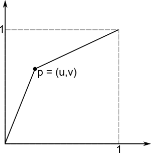
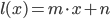
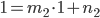
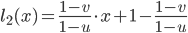
To do perspective correct interpolation manually one can interpolate (u/w) , (v/w)  and (1/w) instead and compute u = (u/w)/(1/w)  in the pixel shader. This is what happens to the coordinates in the listing. I only correct the "long" direction of the ray and let the short uncorrected. The solution created stable lines but with the artifacts from picture one.

GridWPerspective

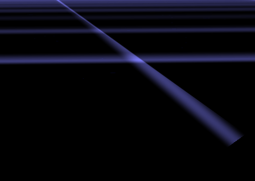
With perspective correction

During writing this post I discovered that my zoom invariant scaling caused this problem. I do not recommend using it. If you need it rather set  c_fLineWidth  to a value which depends on the object distance. I removed the scaling and the semi-correction after writing this.
Lesson learned: Write down what you did to see what you can improve.

Designing a Function

From time to time you need a function in procedural content generation. A function with certain properties which can be edited easily. A function of your own design.

First of all you need a tool to plot functions or create triangulations (for 2D/3D functions). I took GNU Octave to design the following functions and than ported the code.

Lets start with a small example. Later I will show you a more complex variant I designed for sound synthesis.Func_Example1

A good start is a picture. Draw it and think about what should happen for a wish list of parameters. Lets assume we would like to have a function which starts at and ends at . Inside this box we would like to set one point which is on the function. This is a standard interpolation problem but it is a good example and an element of the complex function we will see later.

In next step I always think about other functions which approximate my picture: exp, log, polynomials, sin, cos, ...
Well for our example a line will suffice. The only problem: it must have a break. The easiest thing is to use two lines and somehow combine them.

The first one goes through and its slope is well defined by . The second one can be defined by a view on the upper corner. Again the slope is a simple quotient which can be put into the line equation and gives


Now we could create a piecewise-defined function or use. The second variant is valid only for the upper left triangle. It might be useful for another parametrization or function.

My Universal Periodic Function

I searched for a function with a small parameter set which can:

  • Create high frequent basic tones
  • Be used for fading of different frequencies
  • Be used as fade function for the volume

I started with following ideas: A function for a sound must be periodic. I choose as the domain for one period and a co-domain of because then we have a good control later when using this function. To get something periodic in the interval we could use fmod or just the fractional part. As long as we define a function in the given interval we do not need to think about periodicity.
Furthermore I would like to be able to mix any standard periodic function (Sinus, Triangle, Square, Sawtooth) by setting parameters. I designed 3 parameters to achieve that:

Func_ShapeShape: Just interpolate between Sinus and Triangle function. This can be seen as smoothness parameter too. The implementation is as simple as the idea. The triangle function is designed from three lines with slopes 4, -4 and 4 again.


Stretch: Func_StretchAdd some space at the vertices of the base functions. This can be used to create a Rectangular function or it is useful for volume and frequency fading too. Just take the first half and you have a function which fades in and out and keeps one level in between.


ShiftFunc_ShiftMove the vertices left and right (point symmetric). Values near -1 or 1 create a Sawtooth function. Again using only the first half this can be used to control fading.

Moreover Stretch and Shift can be used to design Attack, Sustain and Release of a note. This is not the full ADSR model, but if I can use the same function on many levels it is a good compromise.

Implementation

I started with the implementation of the shape factor. Here I had no better idea than a simple interpolation. The Triangle wave consists of three linear functions: . To combine them one could use branches for and , but I expect the usage of min/max to be faster. This time there isn't any parameter which disturbs the ordering of the functions as in the example above.

Afterwards I added the stretch factor. Therefore we must solve the problem: How can we add space at the points 0.25 and 0.75?
Easier is to think: How must x look like that sin(x) will have these plateaus?

Func_Stretch2So if we have a function as on the picture we are ready. Applying it to x before calling upf(x) adds the plateaus. Moreover we don't need to bother about the shape factor. Its functionality is orthogonal so we can change the parameters independently.

This trick to remap the input is like changing the contrast in a picture. All we need is a monotonous function and we can change the out coming function while staying inside the given range.

In the implementation I just focused on one single step in , copied that and added 0.5 to the right side.

Func_Shift2Last of all we will add the shift parameter the same way as the stretch parameter. Again a picture can explain that best. Essentially we are using the example from the introduction but we choose the point . For the right side the same slopes can be used again so three lines (two with the same scope) are created from the one point.

Holding is important because we want the shift to move the vertices and no arbitrary points. At the point where the remapping returns 0.25 the vertices are created later which is where we want the change in frequency to happen. I also tested a smoother (exponential) step function but it was less controllable.

This time I consider branching as faster. It is also important to guarantee stability. For parameters -1 and 1 px gets 0. For both cases the branching will end up in the middle part where everything works fine. Otherwise we could get a division by zero.

Summary

Taking all together we have a really customizable function.


Except the function shown here I earlier created a light falloff function without a singularity and a determined radius... I could get used to build my own functions. Finally I will give you a list of things I learned:

  • Use a tool which can plot functions.
  • Always draw your idea of a function on a paper and than try to find an approximation.
  • You should know graphs of functions as: sinus, tangents, exp, gauss, ln, polynomials, ...
  • Linear functions are your friend for parametrization: you will exactly know what they will do.
  • Many things can be achieved with a polynomial: If you have enough criteria as fixed points and derivatives you can just solve some equations to find the proper factors for a fitting polynomial

Dual Contouring

The basis for many model generators is an algorithm to turn an implicit surface into a mesh. I implemented different algorithms over the last years and found the famous Marching Cubes painful. There is a bunch of lookup tables and optimizing it creates even more lookup tables. It has to be said that I always try to create vertex and index buffer which means the algorithm must find adjacent triangles fast. However it took me 500 lines code to implement that. This year I discovered another algorithm: Dual Contouring (Marching Edges would fit as name too). I required 200 lines of code to implement it and the performance/quality is good. Dual Contouring creates nicer meshes (more regular triangles) but produces artefacts if objects become too small, which Marching Cubes also do.

The method was invented 2002 and published on the Siggraph: Dual Contouring of Hermite Data. They also compare this method to marching cubes. You might have a look at the pictures to see the differences.

The Idea

In simple words: span a grid, check each edge, if one vertex of the edge is inside and the other outside create a quad perpendicular to that edge, project quad to the isosurface.

Ok the first step is to take a search grid. This grid has some resolution in each direction and determines the detail of the resulting mesh. Whereby cells of that grid must not necessarily be cubes.

DualGridThen we just compute the signs for each grid point by sampling of the density/distance function. An edge cuts the isosurface if the two adjacent grid points have a different sign. In that case create 6 new vertices for two triangles spanning a quad. We will resolve the adjacency later. The quad is located at the edge's center and has the same size as the grid in the two perpendicular directions. Assume the green grid to be the edge set of the resulting quads. Rendering that mesh directly creates a voxel-like surface. As the grid image shows the created mesh and the search grid are dual graphs. That is where the name comes from.

DualCountourVoxels

Now, only the projection is required. Technically this is done by a gradient descent or conjugated gradient descent algorithm. The gradient might be given by the implicit description of the model or can be estimated by finite differences. Following code snipped computes a variant of the gradient with modified length. If  _bLocalLength == false  this method returns the normal vector for the vertex at this location. Otherwise the length is scaled by the density value which speeds up the whole gradient descent process by a large factor (~8).

Doing this on the created triangles directly would mean to compute everything 6 times in average, since at each corner of a "voxel" six triangles meet. Further we would like to have a Indexbuffer for that model to reduce mesh size and increase rendering performance. So there is one intermediate step to find adjacent triangles.

Find Adjacency

Again it just needs a simple idea: Take a hash map, put vertices into, on collision map indices because we have two equal vertices. The main problem is to find an hash function for vertices, which projects very similar vertices to the same value and different vertices to diffferent values. The former is required because there could be little floating-point mistakes. The best thing here is to round the position to three digits and hash the rounded values. Indeed my function looks much more wired because it failed a lot for other meshes (from explicit surfaces). The hashing is still not perfect.

The  MeldVertices  method takes less than a thousandth part of the whole surface extraction process and increases the performance for everything after that step. It could also be used as post process for marching cubes results and other methods.
It should be mentioned that the upper method will fail for more than 8 hash-collisions between different vertices. This small drawback comes from the fact that the implementation is designed for demo (exe files with less than a couple of Kilobytes). You might want to use  std::vector  for the bucket or even some tree or  std::unordered_map  for the whole hashing.

Now one last image of the beautiful mesh:

DualCountourProjected